The remote sensor is a combination temperature and humidity sensor only. It is designed to be mounted within the wine cellar and can be used in combination with the remote interface controller or up to two additional remote sensors to read and control multiple areas within the wine cellar.
Mounting the Remote Sensor
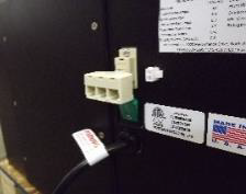
- Disconnect the communication cable from the side of the Wine Guardian unit and the remote sensor. Install the communication cable within the wall and/or ceiling structure of the wine cellar to the desired controller mounting location. (Fig. 1)
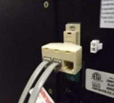
IMPORTANT: A splitter device has been supplied in the remote sensor kit. The splitter device must be mounted at the Wine Guardian unit as shown. DO NOT mount the splitter device at the back of the remote interface controller or to the back of the remote sensor as this WILL cause component or system damage.
- Mount the remote sensor on a solid surface away from doors, corners, air outlets, drafts or heat generating equipment. Do not mount the remote sensor directly on an outside wall or wall adjacent to a warm mechanical room. Use a piece of foam insulation behind the sensor to insulate it from hot or cold surfaces. The recommended height is 4 to 5 feet above the finished floor.
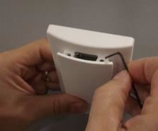
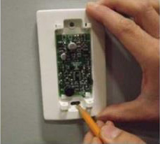
- Remove the sensor cover plate by removing the two Allen head screws at the top of the cover using the Allen head wrench provided in the kit. (Fig.2) Mark the mounting points at the desired location within the wine cellar. Also mark the location of the communication cable connection as this area will require sufficient clearance (1½” hole) in the wall for flush mounting of the sensor plate.
- Drill two 1/8” holes and insert anchors (provided) within the mounting surface. Anchors may not be required if securing to a wall stud or racking system. (Fig. 3)
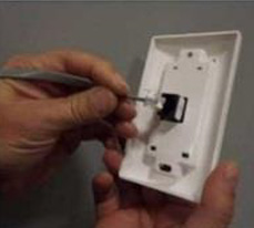
- Plug in the communication cable to the back of the remote sensor and attach to the wall using the two screws provided in the kit. (Fig. 4)
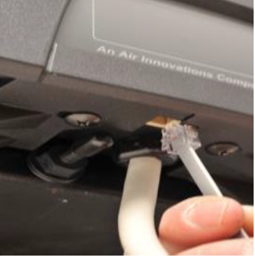
- Plug the remote sensor cables into the splitter device at the Wine Guardian unit along with the communication cable for the remote interface controller. (Fig 5 for ducted models, Fig. 6 for Through-the-Wall models.)
NOTE: If using multiple remote sensors in one wine room, continue to mount the remaining sensors before installation of the sensor cover plates. When multiple sensors are used, the sensor jumper position must be adjusted in order for proper averaging of temperature and humidity readings. See back for jumper set up.
Joining the Communication Cable
IMPORTANT: Wine Guardian cooling systems are supplied with 50 feet of Cat 3, 6-wire, twisted pair communication cable with RJ11 type connectors. Caution must be taken when connecting two lengths of communication cable (splicing) to ensure uniform wire color before and after splice. An RJ11 Modular 6 wire STRAIGHT THROUGH type coupler is the ONLY coupler approved for splicing Wine Guardian twisted pair communication cable.
Changing Jumper Positions
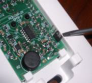
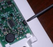
If using multiple remote temperature/humidity sensors in your application, refer to the photos showing the need to change the jumper locations internal to the control board on each remote sensor (up to three maximum).
For the control to average all the sensors utilized (if more than one), the jumper must be in different positions on the pins.
There are three pin settings. To access the jumper: Remove the two-set screws holding on the plastic cover. This procedure allows the control to go to each remote sensor in sequence to average. Failure to perform this procedure will result in the system reading only one sensor and not the average of multiple sensors.
NOTE: If multiple sensors control the Wine Guardian unit, change factory default in configuration setting 10 to “averaging”. The access code at Setting 8 is 12.

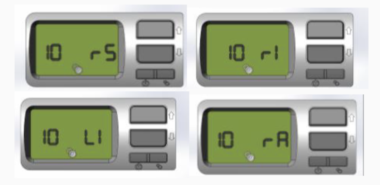
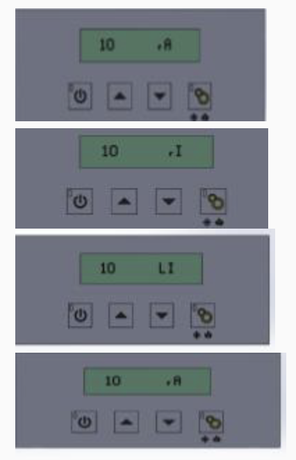
Set up remote sensor or remote interface controller
Setting 10
- Press “Settings” button to advance to Setting 10.
- Press the “Up” or “Down” arrow buttons to adjust to the desired setting.
rS = Remote sensor
rI = Remote interface
LI= Local interface – Through-the-wall unit only rA = Averaging – Jumper position within sensors must be adjusted.