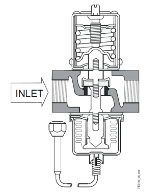
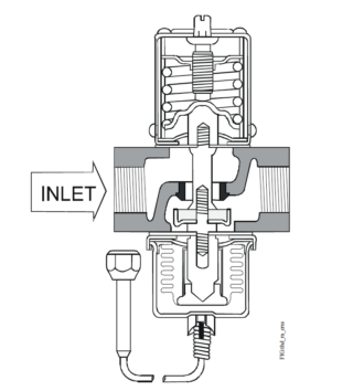
The V46 pressure-actuated modulating valves come in two types of control action: direct acting or reverse acting. Direct-acting V46 valves are typically used for regulating refrigerant head pressure in water-cooled condensers. Reverse-acting V46N valves are typically used for bypass service on refrigeration systems and heat pump applications. Commercial V46 valves may be used with standard non-corrosive refrigerants. V46 models are also available for ammonia refrigerant. For applications where the coolant may be corrosive to the valve trim, maritime models are available, which have nickel copper (monel) valve trim.
| Features | Benefits |
|---|---|
| No Close Fitting or Sliding Parts in Water Passages | Provides robust control in less than ideal conditions. |
| Corrosion Resistant Material for Parts that Come in Direct Contact with Water | Promotes longer valve life. |
| Accessible Range Spring | Allows easy manual flushing, if required. |
| Take-apart Construction | Allows access to interior of valves without removing the valve from refrigeration system or pumping down. |
| Pressure-balanced Design | Maintains consistent setpoint against both gradual and sudden water pressure changes. |
Application Overview
The V46 direct-acting models open on an increase in pressure. Models A, B, and C are typically used for regulating water-cooled condensers, while the low flow D model is generally used in ice machines. The reverse-acting V46N valve model closes on an increase in pressure and is typically used for bypass service on refrigeration systems and heat pumps that control water temperature. Commercial V46 valves are available in 3/8 in. through 2-1/2 in. sizes. Commercial all range models (3/8 through 1-1/2 in.), may be used with standard non-corrosive refrigerants, or ammonia refrigerant applications, depending on the model. V46 Series valves also come in models designed for Navy or maritime salt water applications. These valve bodies are constructed of bronze, and any metal parts that come into contact with salt water are constructed of nickel copper (monel), which withstands the corrosive action of salt water.
IMPORTANT: The V46 Pressure-Actuated Water- Regulating Valve is intended to control water flow under normal operating conditions. Where failure or malfunction of the V46 valve could lead to personal injury or property damage to the controlled equipment or other property, additional precautions must be designed into the control system. Incorporate and maintain other devices, such as supervisory or alarm systems or safety or limit controls, intended to warn of or protect against failure or malfunction of the V46 valve.
Valve Sizing
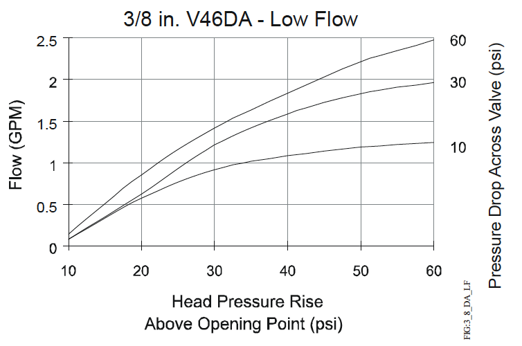
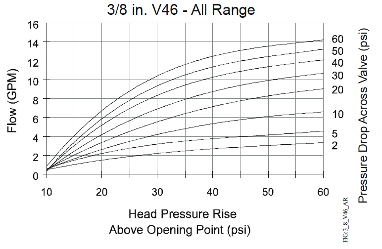
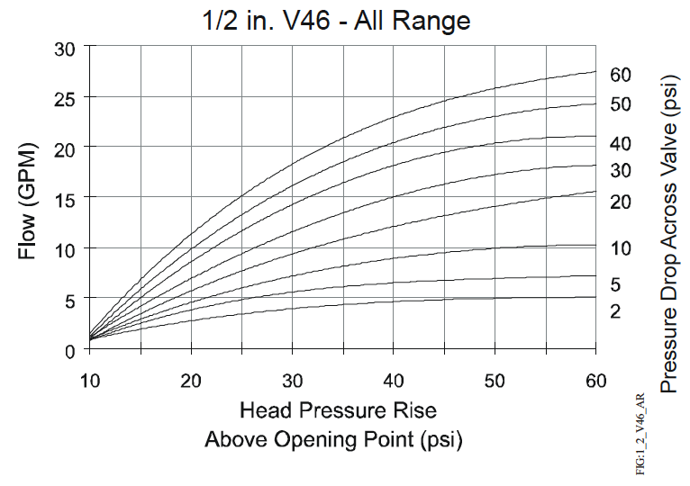
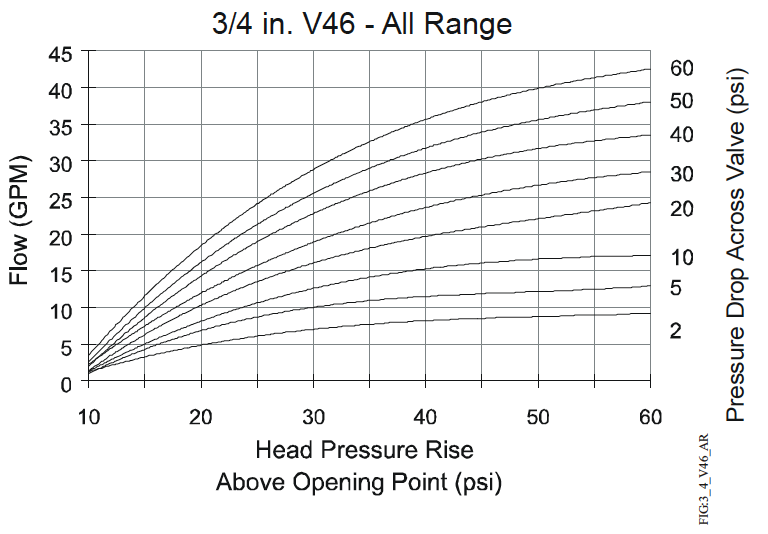
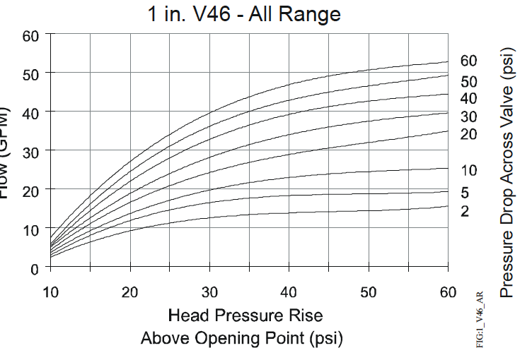
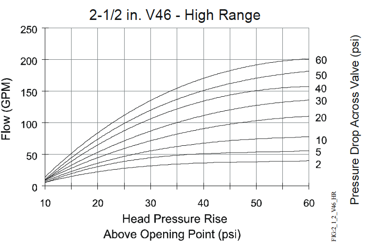
Follow Steps 1 through 3, and use the information obtained to locate a point on one of the flowcharts found under V46 Flowcharts that satisfies all three steps.
1. Determine maximum water flow required using tables provided by the manufacturer of the condensing unit, or calculate the flow using the following formula:
Flow (GPM) = (Tons of Refrigeration × 15,000) / (500 × (outlet – inlet temp) )
Note: If the outlet water temperature is unknown, assume it to be 10°F below the condensing temperature. Example: A 9-ton capacity system has an inlet water temperature of 65°F and an outlet water temperature of 95°F. The maximum required water flow is:
Flow (GPM) = (9 × 15,000) / (500 × (95 – 65) )
2. Determine refrigerant head pressure rise above the valve opening point.
- Valve closing point (to assure closure under all conditions) must be the refrigerant pressure equivalent to the highest ambient air temperature the equipment will be subjected to in the off cycle. Read this in psig from a Saturated Vapor Table for the refrigerant selected.
- To determine the valve opening point, add about 7 psig (48 kPa) to the closing point.
- From the same table, read the operating head pressure corresponding to the selected condensing temperature.
- Subtract the valve opening point from the operating head pressure. This gives the head pressure rise.
3. Determine water pressure drop across the valve. This is the pressure actually available to force water through the valve.
- Determine minimum water pressure available from city mains or other sources.
- From condensing unit manufacturer’s tables, read the pressure drop through condenser corresponding to the required flow.
- To the value found in 3b, add the estimated or calculated drop through installed piping.
- Subtract the total condenser, piping, and static head (if applicable) pressure drop from the available water pressure found in 3a. This is the available pressure drop across the valve.
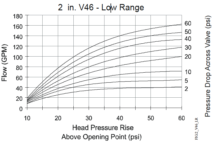
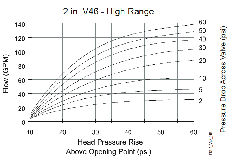
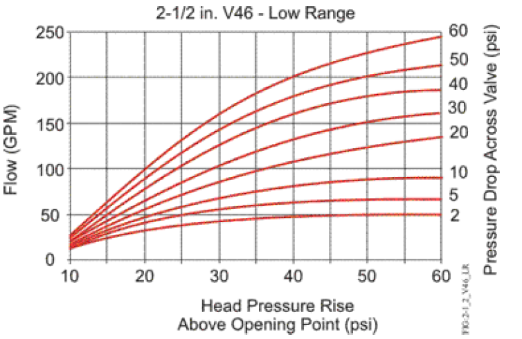
4. Select the proper valve size from the V46 flowcharts by locating a point on a chart that will satisfy the flow, the head pressure rise above opening point, and the pressure drop across the valve.
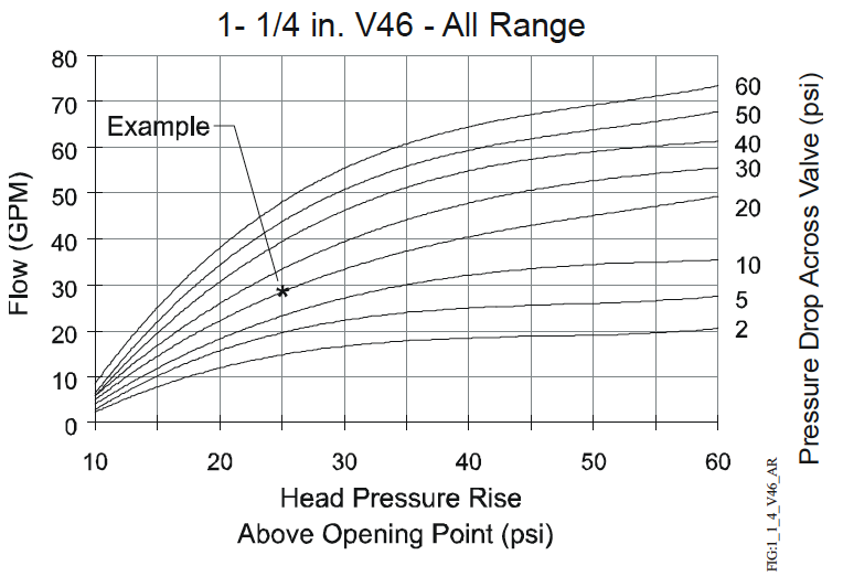
Example: The required flow for a low-range system is found to be 27 GPM. Condensing pressure is 125 psig, and the maximum ambient temperature is estimated at 86°F. City water pressure is 40 psig and the manufacturer’s table gives a pressure drop through the condenser and the accompanying piping and valves at 15 psi. Drop through the installed piping is approximately 4 psi.
- Step 1: 27 GPM
- Step 2: Closing point is pressure of refrigerant corresponding to 86°F = 93 psig Opening point = 93+7 = 100 psig Operating head pressure = 125 psig Head pressure rise = 125-100 = 25 psi
- Step 3: Minimum pressure = 40 psig Pressure drop through condenser = 15 psi Combined pressure drop = 15+4 = 19 psi Pressure drop across valve = 40-19 = 21 psi
Using a flow of 27 GPM, a head pressure rise of 25 psi, and a pressure drop across the valve of 21 psi, the only valve that satisfies all three criteria is a 1-1/4 in. valve. See the 1-1/4 in. V46 – All Range chart on the next page.
V46 Flowcharts
The maximum differential water pressure across a valve is 60 psi.

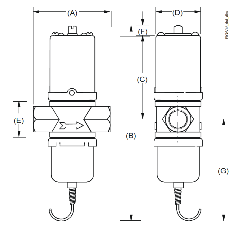
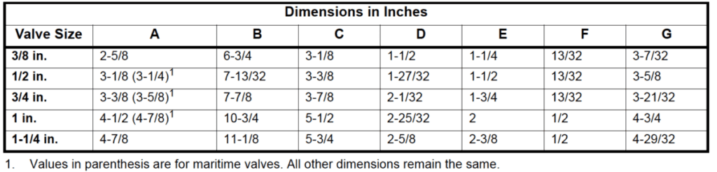
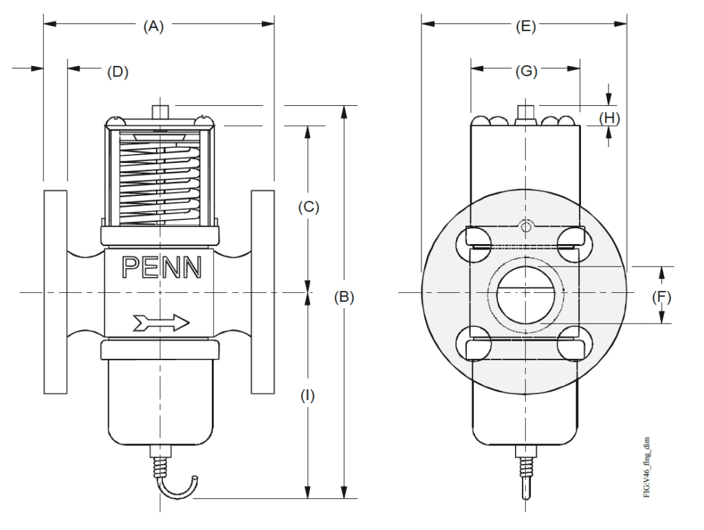
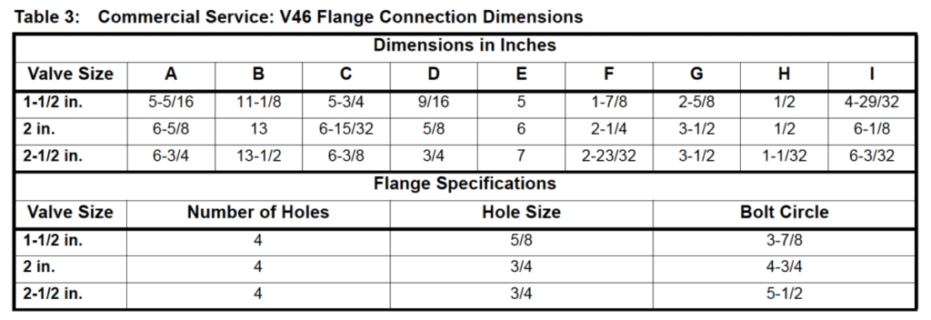
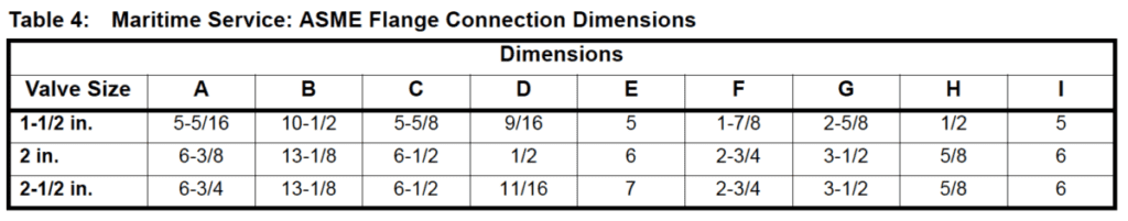
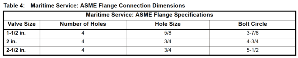
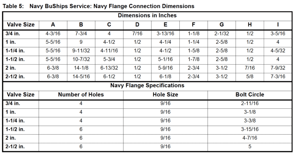
Dimensions
Mounting
Flush water lines to clear any foreign matter that may interfere with valve operation. Mount valves vertically on the inlet side of the condenser with spring housing up. If it is necessary to keep the condenser flooded with coolant, the valve can be mounted on the outlet side. When mounting the valve in a position other than vertical, follow the instructions of the equipment in which the valve will be installed. Make refrigerant head pressure connection to bellows. If additional capillary tubing is required, use 1/4 in. O.D. tubing or larger.
CAUTION: Risk of Environmental and Property Damage.
Coil and secure excess capillary tubing away from contact with sharp or abrasive objects or surfaces. Vibration or sharp or abrasive objects in contact with capillary tubes can cause damage that may result in loss of element charge, which may result in damage to the environment or property.
CAUTION: Risk of Environmental and Property Damage.
Avoid sharp bends in the capillary tubes. Sharp bends can weaken or kink capillary tubes, which may result in refrigerant leaks or restrictions of flow.
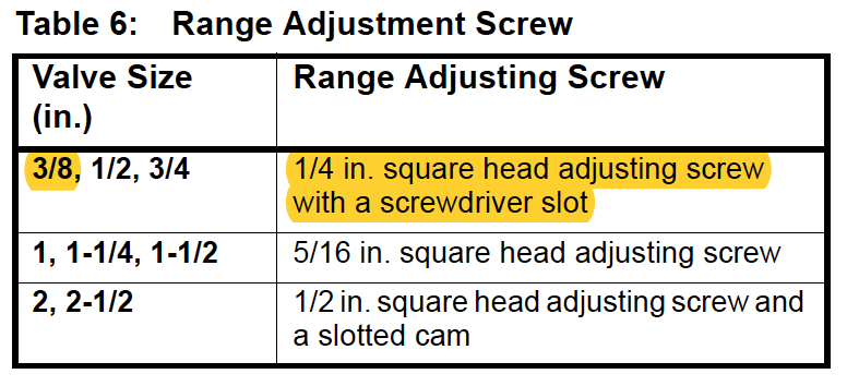
Adjustment
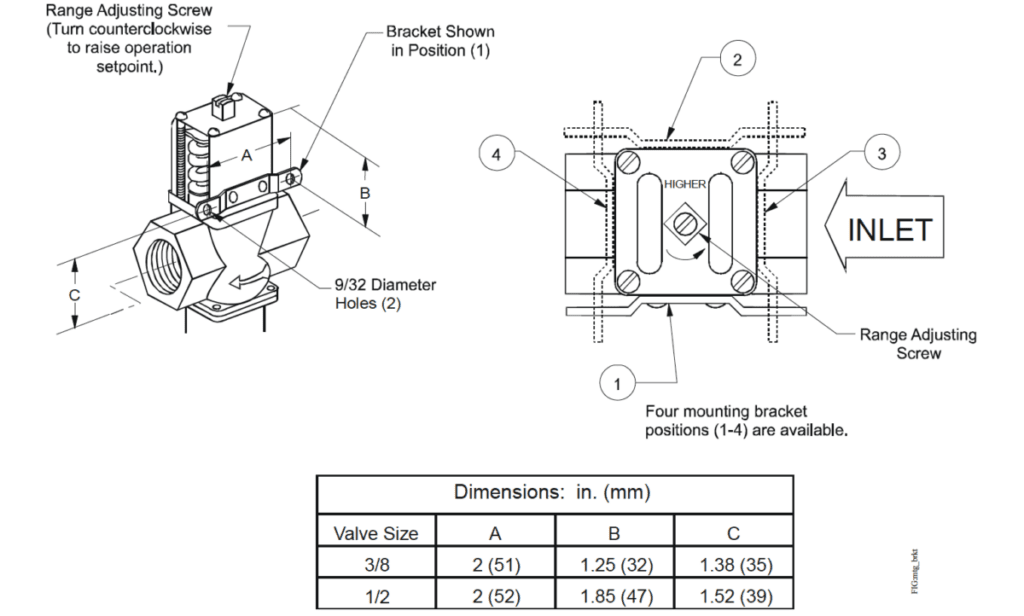
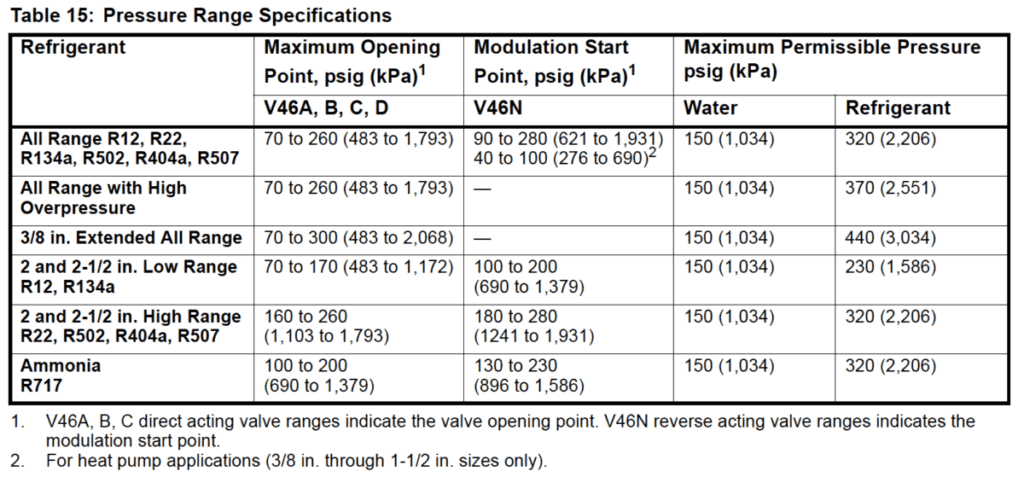
Valves may be adjusted with standard service valve wrenches or screwdrivers; see Table 6. All range valve settings can be changed quickly from low-range refrigerants, such as R134, to high-range refrigerants, such as R22, or from high range refrigerants to lowrange refrigerants. To raise the valve opening point, turn the adjusting screw, located at the top of range spring housing, counterclockwise. See Table 6 and Figure 19. Turn the adjusting screw clockwise to lower the opening point. Exact settings can be made using a pressure gauge in the refrigerant line to determine the throttling point. Put the system under normal operating load and adjust to the desired operating pressure. See Table 15 for pressure range specifications.
If the compressor operates in high ambient temperatures, head pressures may remain high enough during off cycles to prevent the valve from closing completely. In such instances, the opening point of the valve should be raised just enough to cause the valve to close during compressor standby periods. This will also raise the throttling point.
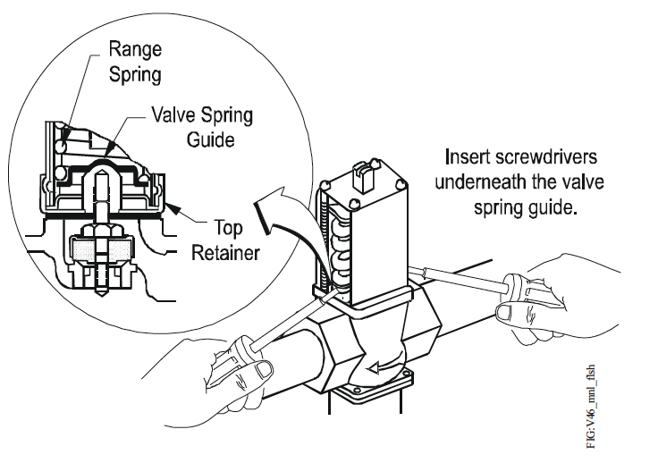
Manual Flushing
To clear any sediment that might accumulate, valves may be manually flushed. Insert screwdrivers under both sides of the valve spring guide and lift upwards to flush the valve. See Figure 19. Manual flushing does not affect valve adjustment.
Repair Data
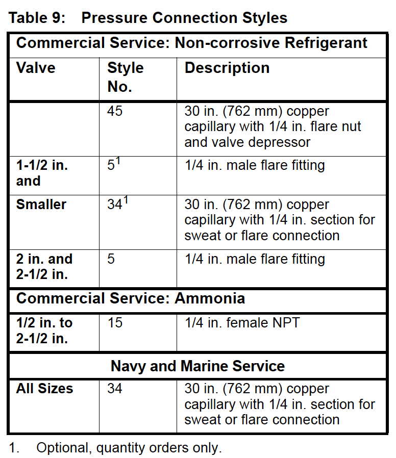
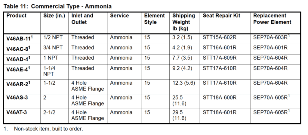
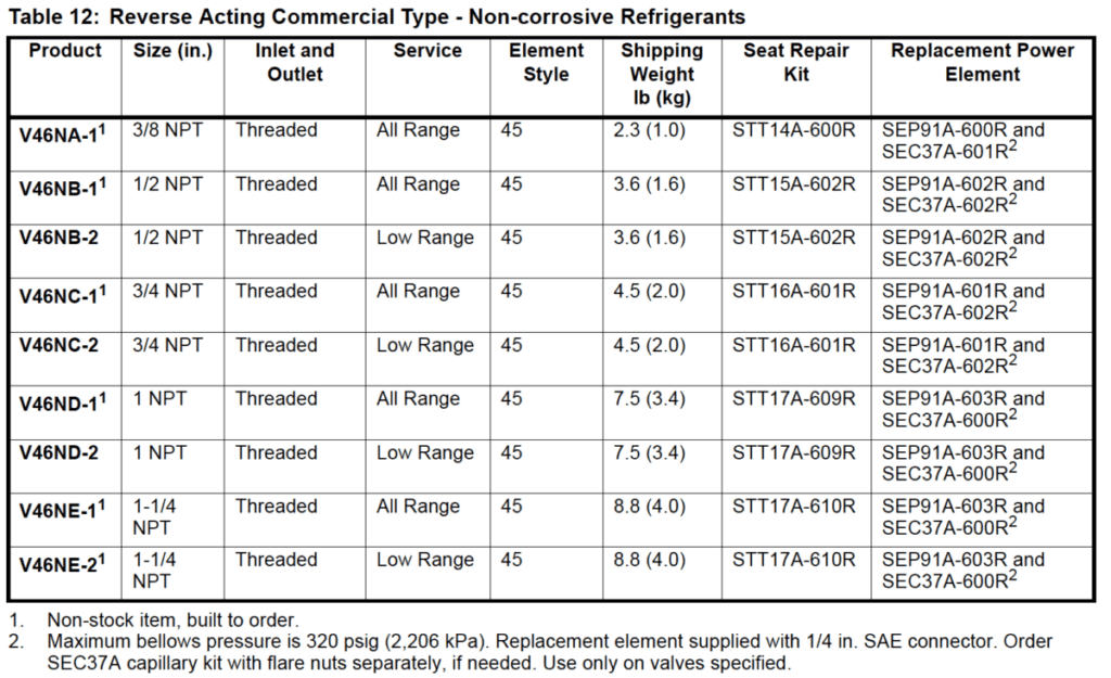
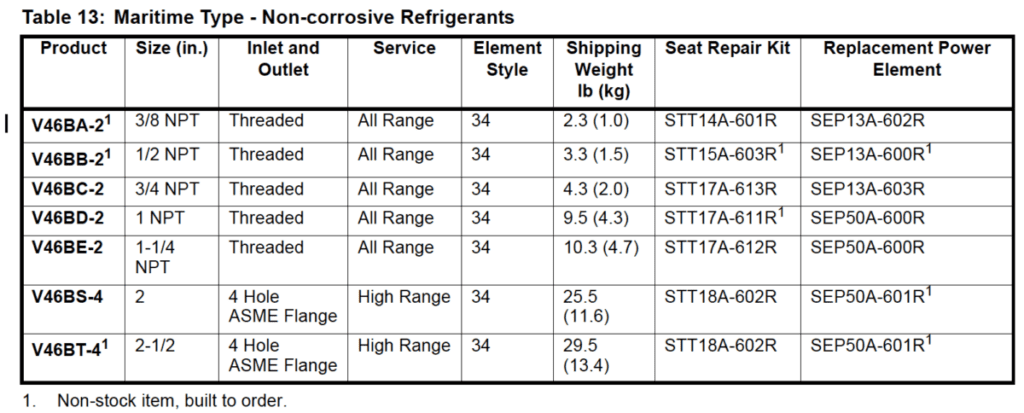
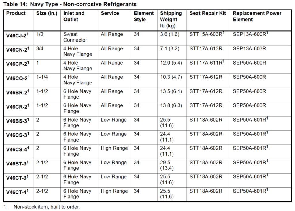
Replacement of the sensing element, internal parts, and the rubber diaphragm can be made. For a replacement valve or replacement parts kit, contact the nearest Johnson Controls/PENN® distributor. For replacement part kit numbers, see Table 9 through Table 14. For replacement kit instructions and details refer to the following bulletins:
- V46, V47, V48, and V49 Sensing Element Replacement Technical Bulletin, LIT-121700
- V46, V47, 246, and 247 Repair Parts and Service Instructions Repair Bulletin, LIT-121695
Ordering Information
When ordering water valves, specify the following:
- Complete product number.
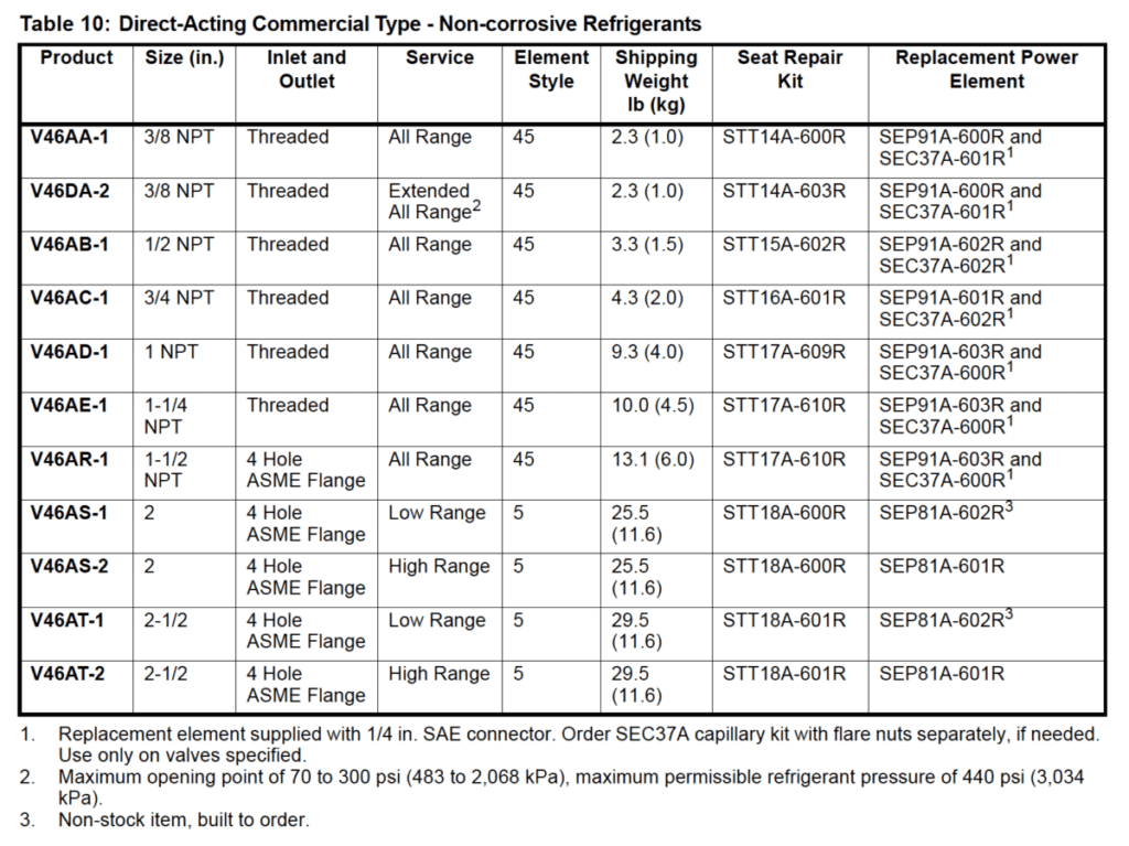
- If product number is not known, answer the following questions and select a valve using Table 10 through Table 14.
- What is the valve size needed? See Valve Sizing section.
- What refrigerant will be used in the system? See Table 15.
- Note: 3/8 in. through 1-1/2 in. valves are supplied with all range construction, allowing a single valve to be used for either low or high range refrigerants.
- c. Is a standard open high, or reverse action close high valve required? See Table 8.
- d. Is a commercial, maritime, or Navy service valve needed? Maritime and Navy valves
- Companion flange kit by part number, if required. See Companion Flanges and Gaskets.
- Mounting bracket (3/8 in. and 1/2 in. valve sizes only) if required, and its position on valve. See Mounting Bracket.
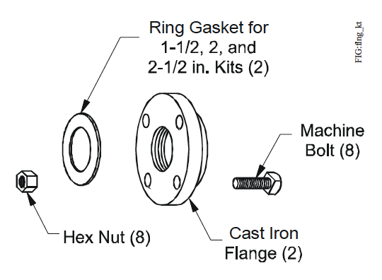
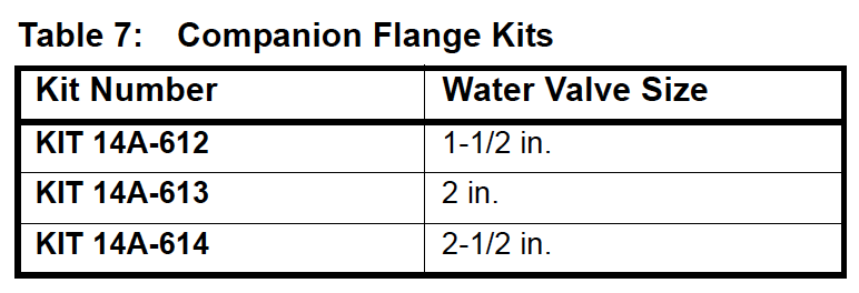
Companion Flanges and Gaskets
Kits are available, at additional cost, for 1-1/2, 2, and 2-1/2 in. flange connection (ASME specifications) valves only. Each flange kit contains two ring gaskets, two cast iron flanges, eight machine bolts, and eight hex nuts.
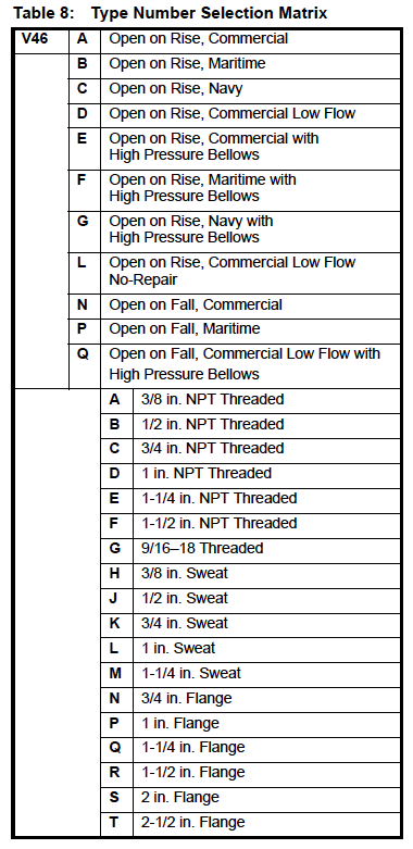
Product Number and Selection
For applications that call for valves not listed in Table 10 through Table 14, Table 8 can be used to specify a custom valve. For example, to order a direct-acting, commercial valve with a 1-1/4 in. NPT threaded connection, specify a V46AE. For more information, contact Application Engineering at (414) 274-5535.
Options
Capillary Tubing Length
Standard length is 30 in. on valves 1-1/2 in. and smaller. Optional 48 in. (1,219 mm) capillary can be furnished at additional cost, when specified.
Mounting Bracket
A mounting bracket as illustrated in Figure 21, is available on 3/8 in. and 1/2 in. valves only when specified. Desired bracket position must also be specified.
Other styles of brackets on 3/8 in. and 1/2 in. valves available on quantity orders. For more information, contact Application Engineering at (414) 274-5535.
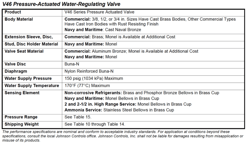
Technical Specifications